
Active Magnetic Field Compensation System
The active magnetic field compensation system with MFC 45 and MFC 90 provides the best possible magnetic environment for your high-tech device and delivers interference-free imaging.
- Scanning electron microscopes
- Transmission electron microscopes
- Electron beam lithographs
- Mask writers for semiconductor manufacturing
- Systems or devices that need a low and stable magnetic environment
Application Purpose and Benefits
The active magnetic field compensation system MFC was developed specifically for electron microscopes and electron beam lithographs based on many years of practical experience. These are mainly used in the areas of research, development, production and quality control. To achieve the best possible results, they need optimal magnetic environmental conditions.
A passive shielding chamber made of nickel-iron alloy (Mu-metal, Permalloy) is very complex and costintensive, alternatively an active compensation system can be used with little effort. It is also possible to operate a less expensive passive shielding chamber in combination with an active compensation system, thus both advantages can be used.

Magnetic Sources of Interference are Usually
- Strong power lines and electric installations
- Lifts
- Subways
- Trams
- Railways
- Cars and lorries
- Earth magnetic field fluctuations caused by solar winds
Strong Power Lines and Electric Installations
Harmonics created by non-linear equipment in the power grid, such as a switched-mode power supply, which are a multiple of the mains frequency, are compensated for by the wide frequency range of the system. Gradients caused by the switching on and off of high-power equipment are also neutralised in the same way.
Compensating Effect in a Sample
The following pictures display the image from a standard sample: Gold on carbon with a scanning electron microscope.
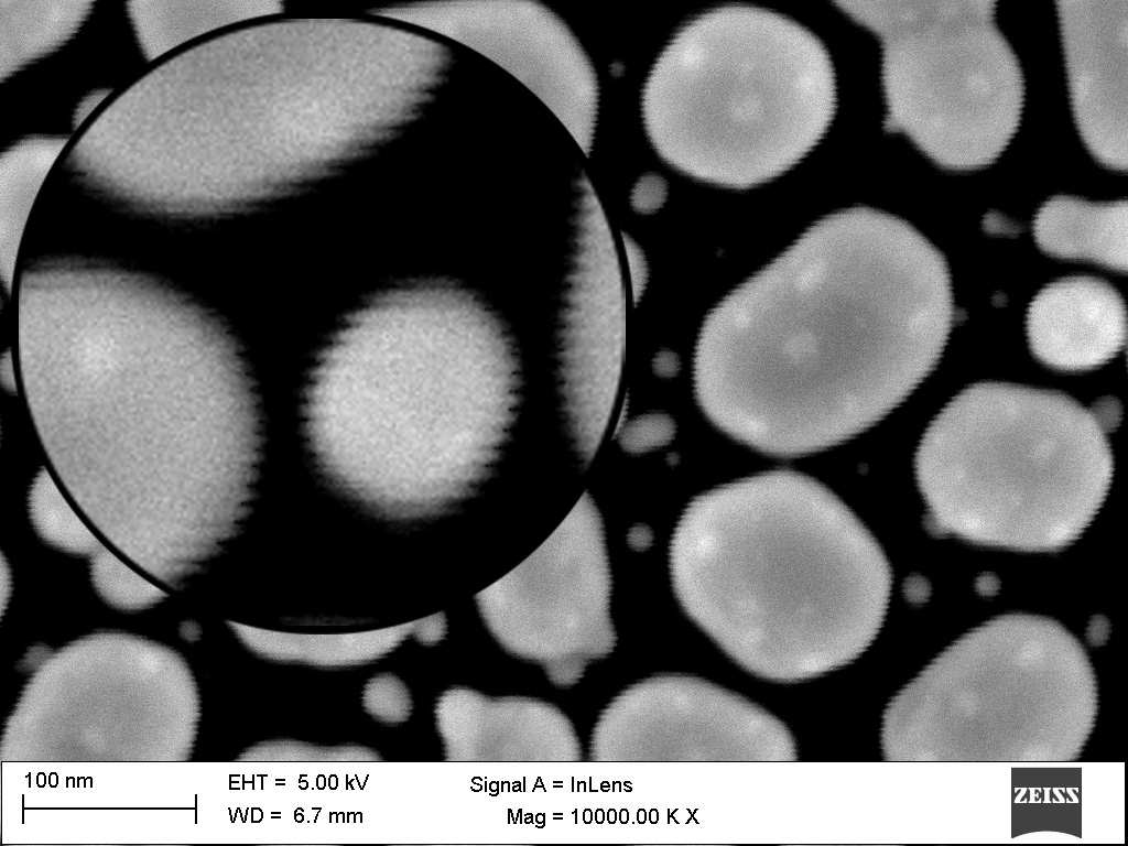
Displays the influence of a 50 Hz magnetic field interference on imaging, triggered by a strong power line in the building.
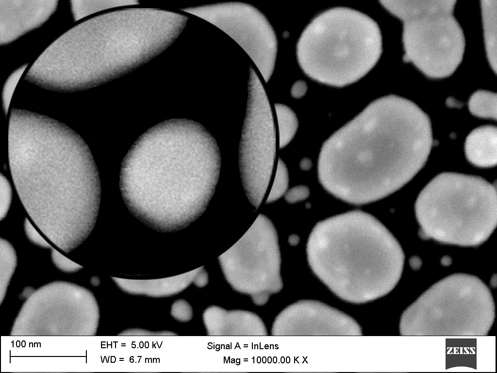
Displays the compensation effect with compensation switched on, resulting in interference-free imaging.
Special Features of the Active Magnetic Field Compensation Systems MFC 45 and MFC 90
- Wide frequency range from 0 Hz to 20,000 Hz in which the system compensates.
- Reduction of the magnetic interference field by a factor of 1,000 (60 dB) at the location of the control sensor in the frequency range from 0 Hz to 1,000 Hz.
- Compensation for very strong magnetic fields up to the earth’s magnetic field.
- Small compact design of the magnetic field sensors.
- Integrated magnetic field measuring system with 100 pT (1 μG) resolution and 126 dB dynamic range.
- Innovative operating mode and visualisation through a touch screen with Help function.
- Acoustic monitoring device for magnetic field signals.
Reduction Factor on the Interference Field
The system processes and compensates for static as well as alternating electromagnetic fields in the frequency range from 0 Hz to 20,000 Hz within a field strength of ± 100 μT (± 1 G).
In this process a reduction of the magnetic interference field by a factor of 1,000 (60 dB) is achieved at the location of the control sensor in the frequency range from 0 Hz to 1,000 Hz.
This means, for example, an interference field with 1 μT (10 mG) is reduced to 1 nT (10 μG).

Maximum Interference Fields
With the appropriate space coil design and the corresponding control device, very strong magnetic fields up to the
earth’s magnetic field can be compensated, whereby with the increase of the frequency of the interference field the
power of the generated counter field decreases.
So that the entire earth’s magnetic field is not compensated, offset operation is possible with both control devices.
In the same way, the compensation of the constant field can be switched off.
Control device MFC 45: approx. 25 μT (250 mG)
Control device MFC 90: approx. 50 μT (500 mG) earth’s magnetic field
Operation and Display
The control device is operated using the built-in touch screen, and there is also a Help function for each function that can be accessed on the right in the menu bar of the display.
The status field at the top of the display displays the switching state of the compensation for each field vector. The
Comp. On button, in the menu bar, switches the compensation on and off. In the main view, the static magnetic field AVG and the alternating magnetic field P-P of the Control Signal are displayed separately. By switching the main view, further measurement data, such as magnetic field strength, coil current, temperature, etc. can be displayed.

Remote Control and Logging
With remote operation via Ethernet, the complete system can be controlled remotely in parallel to the control device’s touch screen. This also enables the logging of measurement data for documentation purposes.
Measuring the Space Coil
For setting the system and checking the space coil, the electrical effective resistance and inductance of the space coil can be measured and determined with the built-in measuring function.
Error Display
Safe operation of the system through function monitoring. All error messages are displayed directly online in the status field of the display and stored in the error memory. Each control loop of the compensation is monitored and measured with a control oscillation detector.
Maintenance-free Operation
Once the system has been commissioned and optimally calibrated, no further maintenance is required.
Acoustic Monitoring Device
With the audio function, magnetic interference signals become audible. This allows an efficient and safe acoustic function test of the control as well as the compensation effect to be carried out. Unwanted control oscillations are thus very well detected and identified, provided they are within the audible range.
Analogue Measured Value Output
Additionally, all measuring signals of the magnetic field sensors as well as the control signals are made available in analogue form for external measuring purposes.
Magnetic Field Sensors
One special feature of the three-axis magnetic field sensors is their small compact design, which makes positioning and mounting much easier. The sensors have a very wide frequency range, extending well into the high alternating field range, within a field strength of ± 100 μT (± 1 G).

Magnetic field sensor detects the direct and alternating field range.

Magnetic field sensor only detects the alternating field range.
The magnetic field sensor is set up and positioned next to the high-tech device using a tripod so that the greatest field reduction occurs in the magnetically sensitive area of the high-tech device. The magnetic field sensor can also be mounted directly on the high-tech device using a pipe system.
Operating Principle
To enable spatial detection of the magnetic field and its compensation, the magnetic field is divided into three field vectors. Individually for each vector, a closed control loop compensates for the interfering magnetic field. The system essentially consists of three components that are connected to each other both electrically and magnetically.

The magnetic field sensor, which is located inside the space coil, detects the interfering magnetic field coming from outside and passes it on electrically to the control device. The control device filters and amplifies the electrical signal and passes it on to the space coil. With the help of the space coil, a magnetic field of equal strength is generated and directed against the interfering
Space Coil
The space coil that generates the magnetic counter field is planned individually for each system. It is adjusted and optimised to the space in such a way that it approximately corresponds to a Helmholtz arrangement for each field vector. The magnetic field sensor and the high-tech device to be magnetically shielded are located inside the space coil.
In order to achieve a large reduction area within the space coil, the space coil is usually laid in the edges of the space. If the room is too big, a cantilevered framework can be used to install the space coil. If several devices need to be magnetically shielded in one room, additional compensation systems can be installed and operated directly next to each other.
The following illustration displays the principle of the spatial setup of the space coil with the magnetic field sensor:

Arrangement of the individual coils for each field vector, shown in colour.
Magnetic axis alignment of the magnetic field sensor to the space coil.
Opposing direction of the magnetic field for each field vector, this results in the cancellation of the magnetic
interference field.
The magnetic field sensor is located together with the high-tech device inside the space coil.
Technical Specifications
Control Device MFC 45 / MFC 90
2 kHz: 251-fold (48 dB)
4 kHz: 63-fold (36 dB)
8 kHz: 15.8-fold (24 dB)
16 kHz: 3.98-fold (12 dB)
32 kHz: 0-fold (0 dB)
Inductance 0 to 477 mH
MFC 90: 3 x 90 W (3,0 A DC)